PDK71304 2×1.0 mm² + 2×2×0.2 mm² 100 kg Robot Joint Cable, 8.7 mm
Robot Joint Cables · Industrial Automation
PDK71304
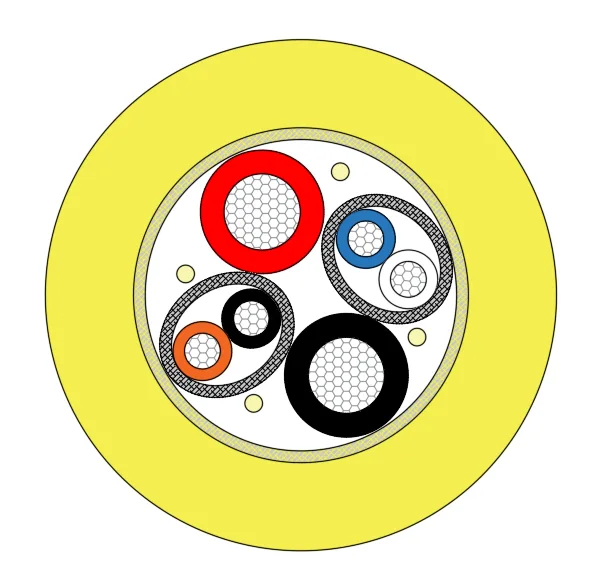
PDK71304 robot joint cable with 2×1.0 mm² power and two 0.2 mm² shielded pairs, Kevlar braid, 1000 N tensile strength, yellow PUR sheath, 8.7 mm OD.
Product overview and use
PAIDE Cable PDK71304-2×1.0mm²+2×2×0.2mm²-100KG is a highly flexible composite power and signal cable for robot joints and pipeline equipment. The construction gathers power cores and twisted signal pairs inside one sheath, so that power and data are provided in a single wiring run, reducing the number of harnesses at joints and along conduit routes and lowering routing difficulty and space requirement. The product is intended mainly for pipeline robots, robotic arm joints, inclinometers and downhole instruments, and equipment working in confined spaces under continuous bending, torsion and dragging. The conductor cross-sections of the power and signal cores are stated in the model designation, while finished outer diameter, insulation and sheath thickness and weight per metre are listed in the construction and materials, electrical performance, and mechanical and environmental sections; this section gives qualitative descriptions only.
Construction and materials
For the conductors, the power cores use tinned copper wire, multi-strand stranded, stranded diameter approximately 1.3 mm; the signal part consists of two pairs, each made up of tinned copper conductors, multi-strand stranded, stranded diameter approximately 0.61 mm. Tinned copper helps suppress surface oxidation in damp and oily conditions and facilitates soldering and crimping.
The insulation is PE throughout. Power core insulation has an average thickness of 0.4 mm and a minimum thickness of 0.34 mm, insulation diameter approximately 2.1 mm, in red and black; signal core insulation has an average thickness of 0.2 mm and a minimum thickness of 0.17 mm, insulation diameter approximately 1.0 mm, in blue-white and orange-black, twisted in pairs. The twisted-pair construction, combined with shielding, supports differential signal transmission.
Shielding is applied to the signal pairs, using aluminium foil plus tinned copper wire braid, which suppresses high-frequency interference and crosstalk well and suits installation in the same harness as servo power lines.
Kevlar is used for filling and reinforcement: 4 strands of 3000D LCP fill the core, and the reinforcement layer is a Kevlar braid with 0.2 mm filament diameter and approximately 50% coverage. The Kevlar carries the tensile load and restrains elongation of the sheath under repeated bending, keeping the cable structurally stable when dragged or hanging under its own weight.
The outer sheath is PUR, yellow, with an average thickness of 1.5 mm and a minimum thickness of 1.3 mm, giving a finished outer diameter of 8.7±0.3 mm. PUR is abrasion resistant, oil resistant and tear resistant, a common sheath material for moving-installation cables, and copes with repeated flexing at equipment joints and with friction inside conduits.
Electrical performance
- Rated voltage: 300/500 V
- Maximum DC conductor resistance at 20 °C: approximately 18.3 Ω/km for the power cores and 84.1 Ω/km for the signal cores
- Characteristic impedance of the signal pairs: 100±10 Ω
- Insulation and sheath thickness are controlled on both average and minimum values, which helps ensure consistent withstand voltage
The DC resistance values above can be used to estimate line drop: for a 100 m power run out and back, the loop resistance is approximately 3.7 Ω, and the voltage at the far end should be checked against the equipment operating current during selection. For signal lines, terminating resistors should be fitted to match impedance and reduce communication errors caused by reflections.
Mechanical and environmental characteristics
- Minimum bending radius: 8-10D for dynamic installation and 6-8D for static installation, where D is the cable outer diameter
- Tensile strength: 1000 N, matching the tensile grade indicated by the model suffix
- Rated temperature: -30 °C to +105 °C
- Reference weight: approximately 100 g/m
Related models in the series
The finished outer diameter, rated voltage, rated temperature, bending radius and tensile strength of this model are listed in the sections above; the other three models in the series are compared below. PDK71300-2×22AWG+4×2×26AWG uses bare copper conductors, PE insulation and a black polyether polyurethane sheath, finished outer diameter 7.1±0.3 mm, DC resistance approximately 55.2 Ω/km for the 0.34 mm² cores and approximately 131.6 Ω/km for the 0.13 mm² cores. PDK71300-1×2×20AWG+ATS 3×2×24AWG-200KG uses a mixed TPEE and PE insulation, 16-strand 1000D LCP braid reinforcement and a black matt TPU sheath, finished outer diameter 9.8±0.5 mm, DC resistance approximately 37.4 Ω/km for the 0.5 mm² cores, with the 0.22 mm² cores at the same DC resistance value as the signal cores above. PDK71303-3×2×0.25mm² is a three-pair signal construction with PE insulation, TPEE sheath and built-in steel wire fillers, finished outer diameter 8.5±0.2 mm, DC resistance approximately 70.1 Ω/km, produced with reference to GB/5023-2008.
The electrical and mechanical figures of the three models compare as follows: both PDK71300 models share the rated voltage of this model and a rated temperature of -40 °C to +90 °C, with tensile strength above 2000 N; the minimum bending radius is 8D for the first and 10D for the second, showing a higher tensile margin at the same voltage class. The three-pair signal model mentioned above has a rated voltage of 300/300 V, a rated temperature of -40 °C to +105 °C, a minimum bending radius of 15D and tensile strength to order. On this basis the user can trade off power cross-section, number of signal pairs and tensile grade.
Typical applications
On pipeline robots and inspection equipment the cable travels in and out of the pipe with the equipment and must withstand wall friction, repeated bending and the hanging pull at the wellhead; the power cores supply the drive motor and lighting, while the signal pairs return video or sensor data. At robotic arm and rotary joints the cable swings with the joint, making the dynamic bending radius a key figure; the dynamic installation design value leaves margin for routing. On inclinometers and downhole instruments the cable is under tension and vibration for long periods, and the Kevlar reinforcement carries most of the load, reducing the proportion transmitted to the conductors and shield. On multi-axis moving platforms and automated equipment, combining power and signal in one cable simplifies drag chain and cable tray layout and makes replacement easier during equipment upgrades. For long conduit runs, the shielded twisted pairs help keep interference coupling low, and the braided armour-style reinforcement further reduces the risk of the sheath being scored.
Customisation and selection notes
Core count, conductor cross-section, shield type, sheath colour and tensile grade can all be customised to project requirements; where higher tensile strength or a smaller outer diameter is needed, the number of Kevlar strands, braid density and sheath thickness can be adjusted. At selection it is advisable to confirm the following at the same time: whether installation is dynamic or static, which determines the bending radius; whether the maximum equipment pull and the free-hanging length under the cable's own weight fall within the rated tensile range; whether power and signal lines run in parallel, which determines whether additional shielding is needed; and whether the long-term operating temperature and contact media match the PUR sheath and rated temperature range. Dimensions and performance figures not stated in the specifications are subject to the specification finally confirmed by both parties.
Related in Robot Joint Cables
Engineering enquiry