Tethered Drone Cable 2x22AWG+2x1 Single-Mode Fiber - 2.9 mm OD, 105 C
Tethered Drone Cables · Tethered Systems
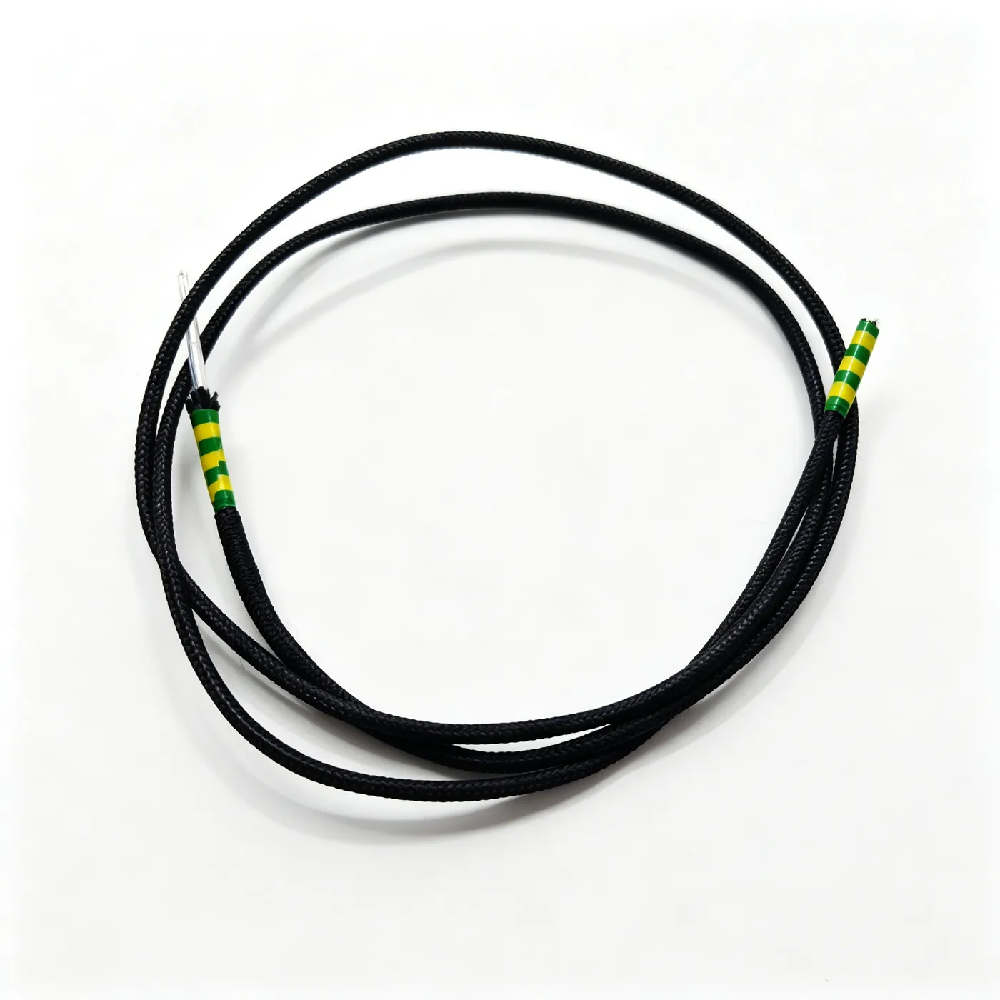
Drone cable 2x22AWG+2x1 fiber
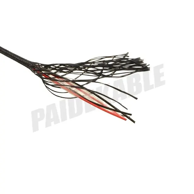
Tethered drone cable with two 22AWG power cores and two tight-buffered single-mode fibers, FEP insulation and fiber braid, 2.9 mm OD.
Product overview
A tethered drone cable is the power and signal link between the ground power supply and the airborne platform. On long-endurance missions it must supply power continuously while returning data, so the design has to balance current-carrying capacity, weight, flexibility and reliability. The lighter the cable, the more payload margin the platform has; the more flexible it is, the less wear on the handling gear and guide sheaves; and the more reliable the construction, the more controllable the performance loss after many deployment cycles.
The tethered drone cable described here uses a composite construction of two power cores and two single-mode fibers, integrating power transmission and data communication in one cable body. Compared with a power-only tether, the composite construction does not rely on a wireless link for data, so it is highly immune to electromagnetic interference and has ample bandwidth; compared with laying fiber and power as separate cables, the single-cable solution reduces the number of attachment points and the complexity of the handling gear and also helps to lower the overall weight.
The cable is built around light weight, flexibility and toughness: the power cores and the fiber units are laid in the same stranded construction, and the outer layer uses a fiber braid as strength member and protection, so the cable keeps a small bending radius and good follow-through while taking traction and repeated handling. The conductors and fibers are positioned in a single cabling pass, which avoids the looseness and slippage of a later second assembly.
Construction and materials
The power section consists of two power cores with 22AWG conductors; the exact stranding and material are subject to the specification document confirmed by both parties and can be selected to the current and flexibility requirements of the project.
- Insulation: FEP, 0.25 mm thick, insulation diameter 1.2 ±0.08 mm
- Core colors: blue and white, to distinguish polarity and connection sequence
- Fiber unit: single-mode single-core fiber, tight-buffered, 0.9 mm diameter, transparent coating
- Cabling: the two power cores and two fibers are cabled with a left-hand lay and fixed with an outer polyester tape
- Outer braid: high-strength fiber braid, 800D per fiber, finished outer diameter 2.9 mm after braiding
FEP, fluorinated ethylene propylene, is notable as an insulation material for stable dielectric properties, a wide temperature range and a low coefficient of friction. These three points match the duty of a tether: stable dielectric properties keep the insulation margin between the power and signal circuits; the wide temperature range keeps the cable from softening or becoming brittle with the difference between airborne and outdoor temperatures; and the low friction coefficient lets the cores slide more freely against each other in repeated bending, reducing fatigue cracking of the insulation. Fluoroplastic also allows a very thin insulation wall, leaving room to cut weight.
The blue and white core colors are a practical detail for connection on site. When the ground station is mated with the airborne equipment, the technician does not need instruments to confirm polarity core by core, and the chance of error drops noticeably. The fiber unit is tight-buffered, and the transparent coating does not change the transmission characteristics of the fiber while giving an outer diameter that can be worked for connectors or splicing.
Cabling the fibers together with the power cores in one pass is the key process step in this type of composite cable. A fiber cannot take tensile load or concentrated lateral pressure, so cabling must keep the pay-off tension of each unit equal and fix the relative positions with a polyester tape wrap, avoiding gradual slippage over many handling cycles that would load the fiber or increase attenuation. Fixing the relative positions in one stranding pass also makes the cable cross-section rounder, so it is less likely to jam during handling.
The outer high-strength fiber braid serves three purposes: it takes the traction load of the cable and moves the pull away from the fibers and conductors, keeping the fiber at low strain over time; it provides abrasion protection against the ground, guide sheaves and payout openings; and it forms a relatively light outer cover that encloses and protects the internal construction without adding significant weight. The braid construction and density can be determined by the actual working load and abrasion requirements.
Key features
- Optoelectric integration: power and data in one cable, so the ground station needs only one set of handling and connection gear
- Light and flexible: thin fluoroplastic insulation with a fiber braid outer cover gives good bending performance for frequent handling
- EMI immunity: data travels over the fiber link and is unaffected by the electromagnetic field of the power cores or by ground loops
- Abrasion and weather resistance: the fiber braid outer layer improves wear and environmental performance for field and vehicle-mounted work
- Stable structure: fibers and cores are cabled together and fixed, so they do not slip during long-term handling
- Flexible connection: color-coded cores, with fiber ends spliced or fitted with connectors to site conditions
Electrical and mechanical performance
- Rated voltage: customizable to the project supply voltage, subject to the specification document confirmed by both parties
- Long-term operating temperature: 105 C, covering the temperature swings of airborne and outdoor operation
- Data transmission: single-mode fiber link, suited to longer-distance, higher-bandwidth data return
- Current-carrying capacity: varies with the selected conductor cross-section and can be configured to the supply power requirement
- Mechanical performance: tensile strength, bending radius and abrasion class are determined by the operating conditions and can be customized per project
In a tethered system the electrical and mechanical performance of the cable are not independent: excessive traction raises fiber attenuation; too small a bending radius ages the insulation and braid prematurely; and insufficient current margin lets the temperature rise of the power cores conduct down to the fiber and outer cover. Selection therefore needs to consider supply power, link distance, maximum pull and handling method together rather than pursuing one figure on its own.
Typical applications
- Long-endurance tethered drone platforms, supplying onboard payloads and ESC systems continuously while returning video and telemetry
- Ground power and communication links for aerostats and tethered balloons
- Rapidly deployed tethered systems on mobile ground stations or vehicle-mounted platforms
- Monitoring and inspection flight missions that need a wired link for transmission stability
In such systems the cable often runs over winches, guide sheaves and payout openings and is rubbed repeatedly, and concentrated local loading is the main source of failure. Besides choosing an abrasion-resistant braided outer cover, the system should be provided with suitable bending radius limits and tension control so that the cable always works within its permitted load range, and the joints should be treated as key inspection points and checked regularly.
Selection and customization notes
- Core cross-section and core combination can be adjusted to the supply power and voltage class
- Fiber type and count can be selected to link distance, bandwidth and redundancy requirements
- Finished outer diameter and weight per unit length can be optimized for aircraft payload and winch capacity
- The outer cover form (fiber braid, or braid plus sheath) can be determined by abrasion and environmental requirements
- Length, joint type and handling method can be customized to the ground station configuration
If a different cross-section, a different core ratio or a finished assembly with connectors is required, please provide the operating conditions and interface requirements and PAIDE Cable will propose a solution per project; specific specifications are subject to the specification document confirmed by both parties.
Related in Tethered Drone Cables
 2×20AWG
 7×0.5
 Drone cable 4×1.2
 PDK41301-4×22AWG
Engineering enquiry