Tethered Drone Cable 4×1.2mm², FEP Insulation, Aramid Braid, 32.3g/m
Tethered Drone Cables · Tethered Systems
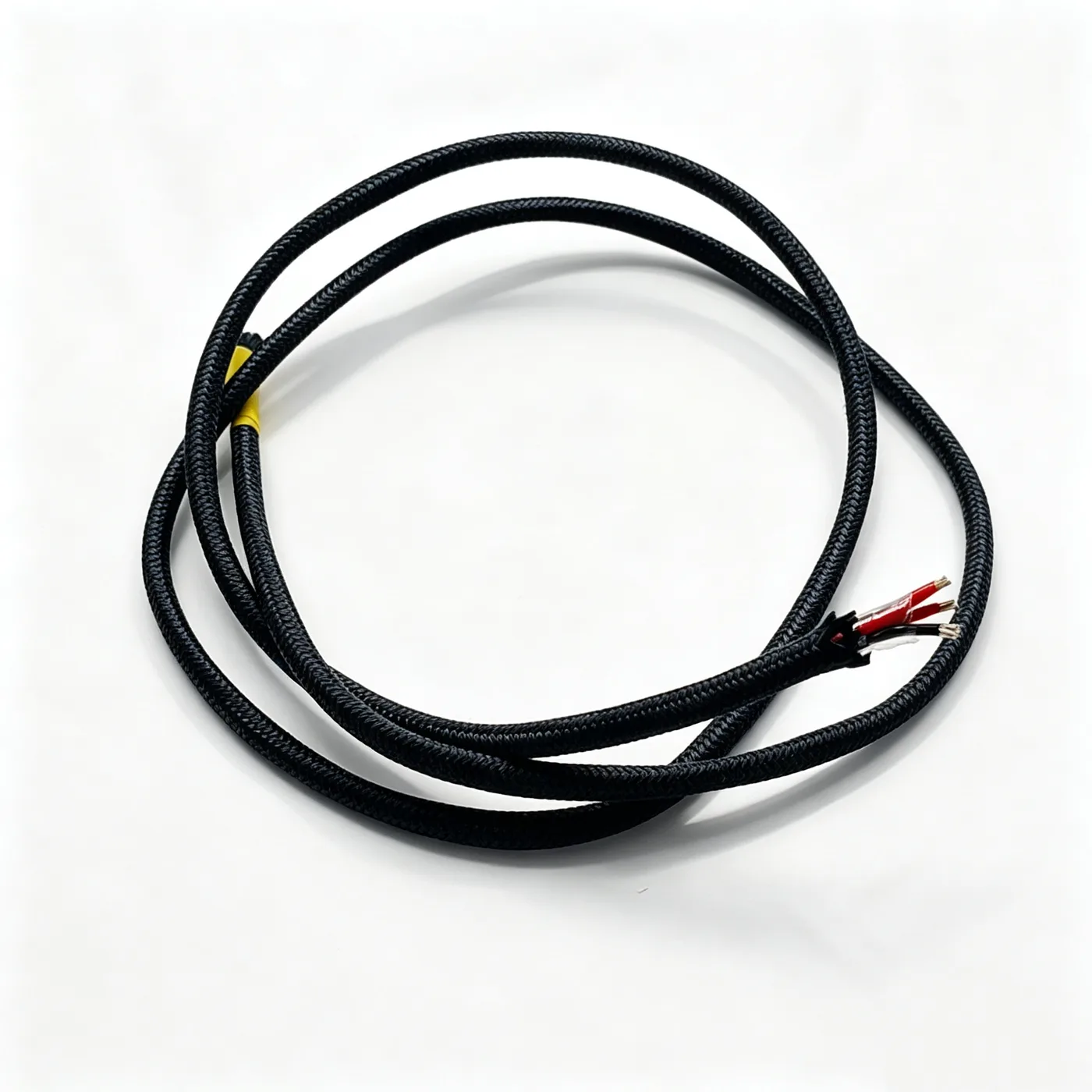
Drone cable 4×1.2
Lightweight four-core tethered drone power cable with alloy conductors, FEP insulation, 16-carrier aramid braid at 99% coverage and 32.3g per metre weight.
Product overview and use
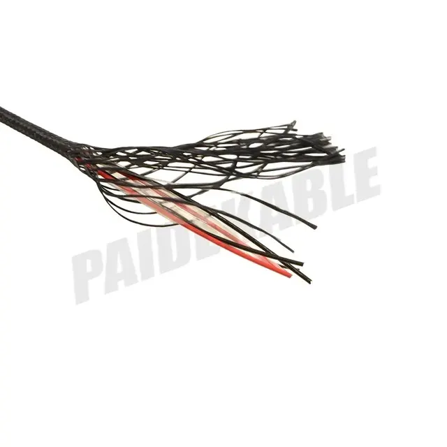
This is a lightweight power cable for tethered drones and lighter-than-air platforms. It has a four-core construction: high-strength alloy wires for the conductors, fluoroplastic insulation, and an outer black aramid braid that carries the mechanical load. In tethered operation the cable stays airborne for long periods, bends repeatedly with the attitude of the aircraft and takes wind load, so the design separates conduction from load bearing — the cores carry power, the braid provides tensile strength and abrasion resistance, and fillers and a wrapping layer keep the core round, so that weight per unit length is kept as low as possible while meeting current-carrying requirements.
For operation where a ground power unit supplies the aircraft continuously and the aircraft stays aloft for long periods, cable weight, flexibility and tensile capability directly determine the usable height and the duration of a single flight. This specification is designed for that kind of duty. The cable can be supplied in the length required, with both ends prepared as agreed.
Construction and materials
- Conductor: alloy wire, 1.2mm² per core, multi-wire stranding, left-hand lay, stranded diameter 1.4mm.
- Insulation: FEP fluoroplastic, insulation diameter 1.8±0.03mm, cores in 2 red and 2 black for identification and wiring at both ends.
- Cabling: four cores cabled to the lay-up drawing with a left-hand lay, core diameter 4.4±0.1mm, PE profiles as fillers between cores and a polyester tape over the core.
- Strength layer: black aramid braid, 2 × 800D yarns arranged 8+8, 16 carriers, designed braid coverage 99%, diameter after braiding 5±0.15mm.
- Outer sheath: can be customised to the project; material, colour and thickness are as stated in the specification document confirmed by both parties.
Alloy wire is used instead of conventional annealed soft wire in order to obtain higher tensile strength at the same cross-section and reduce the risk of the conductor stretching while airborne. Fluoroplastic insulation has a wide temperature range and stable dielectric properties, and meets insulation requirements at thin wall thicknesses, which helps control diameter and weight. The braid uses high-strength fibre with two groups of eight yarns interlaced, spreading tensile load over the whole cable and also resisting external abrasion and scuffing. The fillers and wrapping layer carry no current and take no load, but they determine how round the core is and how stable the internal positions are, which is what keeps the construction from loosening and the cores from shifting after repeated bending.
Key features
- Lightweight: thin-wall fluoroplastic insulation with alloy conductors keeps weight per unit length low for long periods aloft.
- Independent strength structure: tensile load is taken mainly by the high-strength fibre braid and is not transferred to the conductors, which supports a long service life.
- Flexible and easy to deploy: stranding and braid are matched to each other, so the cable is soft and suits repeated coiling, deployment and movement with aircraft attitude.
- Electrical stability: fluoroplastic insulation has stable dielectric properties and consistent insulation diameters, giving a symmetrical construction with balanced performance after cabling.
- Customisable: core count, conductor cross-section, length, braid coverage and end fittings can be adjusted to project requirements.
Electrical and mechanical performance
- Weight per unit length: approximately 32.3g/m.
- Rated voltage, temperature range, minimum bending radius and conductor DC resistance: as stated in the specification document confirmed by both parties.
- Tensile capability is determined mainly by the braid; the mechanical strength of the finished cable can be calculated and confirmed to the operating conditions.
- Core dimensions and braid coverage are controlled by process parameters in production and can be adjusted to actual requirements.
Typical applications
- Ground power for tethered drones: continuous supply from a ground unit over the tether for long endurance.
- Power for lighter-than-air platforms and tethered balloons: a light, tensile and repeatedly deployable power line.
- Emergency communication and lighting relay: power cable for temporarily erected tethered platforms.
- Monitoring and inspection endurance missions: power and associated cabling for equipment that hovers for long periods.
- Research and test platforms: lightweight power lines in project-specific lengths and diameters.
Selection and customisation notes
- Establish the power demand and operating voltage first, then determine conductor cross-section and core count; this specification is a four-core power construction, and the same logic can be extended to other core counts and cross-sections.
- Confirm the flight height and length in use, assess the tensile load the braid has to carry, and increase braid coverage or adjust the number and arrangement of strength yarns where necessary.
- Confirm the deployment method and coiling radius, then confirm the minimum bending radius and the end fitting arrangement.
- Where polarity or multiple supply circuits must be distinguished, different core colours can be used; this specification uses two colours, two cores each, for two circuits.
- Sheath colour, surface marking and packaging can be stated when the requirement is confirmed; final parameters are as stated in the specification document confirmed by both parties.
Related in Tethered Drone Cables
 2×20AWG
 7×0.5
 Drone cable 2x22AWG+2x1 fiber
 PDK41301-4×22AWG
Engineering enquiry