ROV Umbilical Cable 4x24AWG+2x2x26AWG+1x26AWG+2x1SMF+D-635KG - 11 mm OD, 635 kg Tensile
Underwater Power Cables · Marine & Subsea
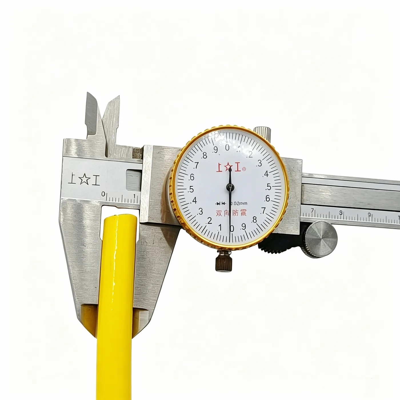
ROV umbilical cable 4x24AWG+2x2x26AWG+1x26AWG+2x1SMF+D-635KG
Buoyant ROV umbilical cable with 24AWG power and control cores, twisted 26AWG signal pairs and two single-mode fibers; 11 mm OD, 635 kg tensile strength.
Product overview
The ROV umbilical cable is the key link between an underwater vehicle and the surface control unit, carrying power to the subsea equipment, transmitting control commands and returning data. The earlier practice was to lay power lines, signal lines and optical fibers as separate parallel cables, which tended to tangle during launch and recovery and complicated the handling gear. An umbilical cable integrates the different transmission units into one cable body, so that a single cable performs several connection tasks and the launch and recovery system can be laid out more simply.
This product adds a single-mode fiber unit to the subsea power cable design, so the cable provides an optical channel as well as electrical power and control signals. The optical channel is highly immune to electromagnetic interference and offers high bandwidth, which suits subsea equipment with large data volumes, such as underwater camera systems and real-time data return from sonar and sensor arrays. Combining power, control and communication in one cable also reduces the number of subsea connectors and therefore the number of potential failure points at subsea connections.
The cable is built to float: a foamed structure inside the sheath compensates the weight of the cable in water, giving it a slight upward tendency when submerged. During deployment the cable does not readily sag onto the seabed, which reduces abrasion and scraping against rocks, wrecks and other obstacles; during recovery it is less likely to be snagged by debris on the seabed, making the operation smoother.
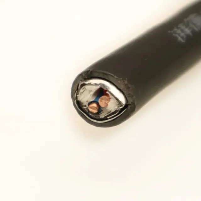
The functional units inside the cable are arranged in separate groups: power cores, twisted signal pairs, the single signal core, the fiber unit and the strength member each occupy their own position in a clear layer structure. This layout reduces coupling and crosstalk between units and makes stripping and connector assembly at the ends easier. The cable has a round profile and a flexible feel and follows the relatively small bending radii of guide sheaves and winches.
Construction and materials
- Conductor: stranded copper strands; power and control cores are 24AWG and signal cores are 26AWG, with the two types laid out in separate groups.
- Insulation: PE; the power cores are color-coded red, yellow, green and black for identification and matching at both ends.
- Cabling: the power cores, two groups of twisted signal pairs, the single signal core and two single-mode fibers (SMF) are cabled in one pass, each unit in its own position to reduce mutual crosstalk.
- Shield: aluminium foil lapped with the metal side inward, a 7/0.15 tinned drain wire included at cabling, and an outer 16-carrier braid for reinforcement with approximately 50% coverage.
- Strength member: 3000D high-strength fiber bundles laid axially along the core; they carry the pulling force and the weight of the cable independently, so the cores and fibers carry no tensile load under normal operating tension.
- Buoyancy layer: inner foamed TPU, 2.4 mm thick, providing positive buoyancy so the cable keeps a slight upward tendency in water.
- Outer sheath: TPU, 0.6 mm thick, yellow with the natural color, extruded; the surface is smooth and does not readily retain mud and sand.
Electrical and mechanical performance
The finished cable has an outer diameter of 11 ±0.5 mm and a round cross-section, so it passes smoothly through guide sheaves, winches and limit devices during launch and recovery. The tensile strength of the strength member is 635 kg; the load path is separate from the electrical and signal paths, so pulling force is not transferred to the power cores, signal cores or fibers.
The insulation and sheath use water-, oil- and abrasion-resistant polymers that do not readily absorb water, harden or crack during prolonged immersion. The fiber unit sits inside the cable core and is enclosed by the shield, the buoyancy layer and the sheath, so it is protected during towing and repeated bending. The cable is flexible and can be coiled and uncoiled repeatedly within the permitted range, which suits operations that require frequent deployment and recovery.
Key features
- Power, control and optical communication transmitted in one cable, reducing the number of parallel subsea cables and connectors;
- The strength member carries the mechanical load independently, so the electrical units and fibers are not subjected to tensile force and the load path is clearly defined;
- Aluminium foil lapping with a tinned drain wire gives a continuous shield path and stable interference rejection for signal transmission;
- The foamed buoyancy layer compensates the weight of the cable in water, leaving the cable slightly buoyant and reducing contact with the seabed;
- The outer sheath resists water, oil and abrasion for repeated deployment, recovery and towing;
- The cable is round and flexible, and end stripping and connector assembly are straightforward on site.
Typical applications
The product is mainly used on underwater vehicles and their support equipment, including power, control and signal connections between remotely operated vehicles and the surface control unit, and also between subsea observation equipment, subsea detection devices and subsea work tools and the surface control end.
In subsea survey and research equipment that requires power, signal and optical transmission in one cable, this construction reduces the cable count and the number of subsea connectors and simplifies wiring; where deployment and recovery are frequent, the buoyant behavior lowers the chance of the cable contacting obstacles on the seabed.
Selection and customization notes
- Core count, cross-section and fiber count can be configured to the equipment interface and control requirements;
- The strength member specification can be determined from the working depth and load conditions;
- Cable color and end preparation can be agreed to project requirements;
- The launch and recovery method and the coiling arrangement can be agreed to the on-site operating conditions.
Items not listed on this page can be customized per project, and all parameters are subject to the specification document confirmed by both parties. For other core counts, cross-sections or fiber combinations, please contact the PAIDE technical team to confirm the configuration.
Related in Underwater Power Cables
 Custom
 Custom
 Custom
 Custom
Engineering enquiry