3x0.75 + STP CAT6 Neutrally Buoyant Power and Data Cable
Zero-Buoyancy Cables · Marine & Subsea
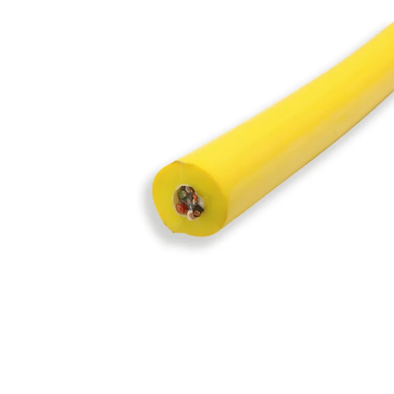
Buoyant cable 3x0.75+STP CAT6
Neutrally buoyant cable with 3x0.75 mm² power cores and a shielded CAT6 data unit, LCP strength members and a 14 mm foamed PUR sheath.
Product overview
Zero-buoyancy cable, buoyant cable 3x0.75+STP CAT6, is a subsea composite cable that carries power and data in one cable body. Power cores and one shielded Category 6 data unit are laid side by side, and a foamed sheath is applied over them; the overall specific gravity is engineered to be close to that of seawater, so the cable is neutrally buoyant in water - it neither sinks and drags on the bottom nor keeps floating up and pulling on the equipment.
It is intended for subsea equipment that stays immersed for long periods, is towed repeatedly or hovers at a fixed point. Three points matter most: whether power and data can be transmitted in one cable, whether the cable body is easy to control underwater, and whether the sheath and shield remain reliable after long immersion. Where the number of subsea connections is to be reduced while the signal return stays stable, this construction is easier to install than laying power and data cables separately, and easier to pay out and coil.
Construction and materials
- Conductor: stranded bare copper strands, nominal cross-section 0.75 mm², 3 cores.
- Insulation: PE, 0.5 mm thick; single insulated core outer diameter approx. 2.0 mm, color-coded red, white and black.
- Data unit: 4 pairs of 7/0.2 twisted pairs with a cross filler, aluminum foil shield, tinned copper braid (coverage approx. 80%) and polyester tape wrapping.
- Cabling and load bearing: cabled core outer diameter 7.8 mm, with 8 × 3000D LCP fibers built in as strength members.
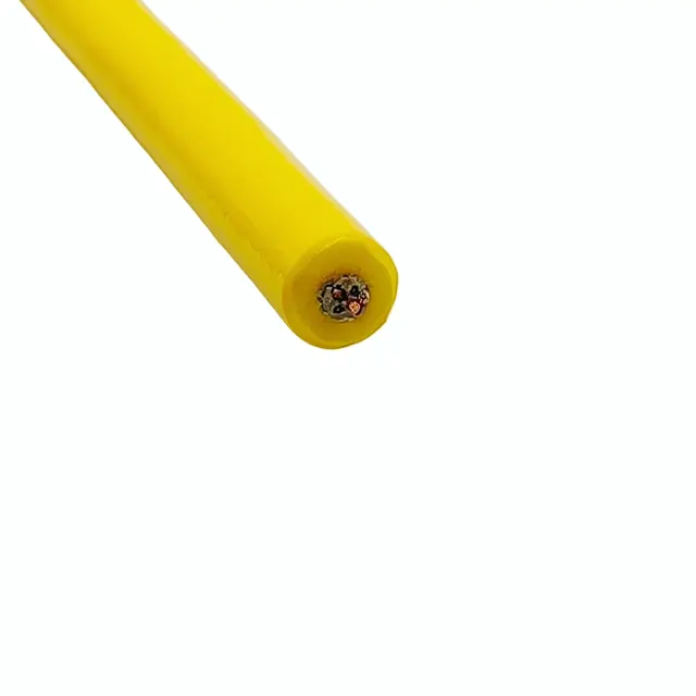
- Outer sheath: foamed PUR, 3 mm thick, yellow; finished outer diameter 14 ±0.5 mm.
The power cores are bunched from bare copper strands, tightly stranded with a round surface for repeated bending; the insulation is extruded solid PE, balancing dielectric strength and diameter control, and the three cores are color-coded so phases can be identified at both ends.
The data unit is cabled in pairs, with a cross filler providing physical separation between pairs; each pair is wrapped in aluminum foil and closed with tinned copper braid. The braid acts both as shield and as an auxiliary strength member, and the outermost polyester tape wrapping holds the assembly together so it does not loosen during installation. Braid and foil form a composite shield that helps reduce external interference and pair-to-pair crosstalk.
The strength fibers are stranded in the same direction as the cores, so the tensile load is carried mainly by the fibers and the conductors are not loaded directly; the cabled core is round and evenly compacted, keeping it flexible without being so loose that cores pull out during towing. The outer sheath is applied in a single foamed extrusion that bonds closely to the core, forming a low-density outer layer while retaining the flexibility and hydrolysis resistance needed underwater.
Key features
- Neutral buoyancy: the foamed outer sheath lowers overall specific gravity, so the cable neither sinks nor floats and keeps a stable attitude when towed.
- Power and data in one cable: power cores and the shielded data unit are installed in a single pass, reducing the number of subsea connection points.
- Interference-resistant construction: aluminum foil and tinned copper braid form a composite shield, and the cross filler reduces pair-to-pair crosstalk.
- Independent load bearing: strength fibers are laid separately from the conductors, so tensile load does not act on the copper strands, giving longer life under repeated pay-out and recovery.
- Water and oil resistant: the outer sheath stays flexible under long immersion and in oily conditions, and resists cracking and water absorption.
- Easy to install: tight stranding and a compactly cabled core make the cable easy to run over sheaves and to coil.
Electrical and mechanical performance
The data unit and the power cores are structurally separated and the shield is continuously wrapped, which reduces interference on the signal return path underwater. Electrical and mechanical values for the complete cable vary with working depth, towing speed, number of pay-out cycles and the connector type used; they can be customized to project requirements and are subject to the specification file confirmed by both parties.
In structural terms, tensile load is carried by the strength fibers while the conductors and shield mainly see the stress of bending during installation, so repeated pay-out within the design conditions does not damage the cores; the foamed sheath provides outer protection and keeps the shield away from direct contact with seawater and silt, which helps extend service life. Where the duty involves greater depth, high towing speed or strong impact, please state this at the selection stage so that the strength configuration can be adjusted.
Typical applications
- Power supply and video or sensor signal return for ROVs;
- Composite cable for subsea pan-and-tilt heads, cameras and lighting;
- Towing line for subsea inspection, sampling and observation instruments;
- Offshore engineering equipment requiring neutrally buoyant attitude control;
- Short working cables matched to subsea wet-mate connectors;
- Temporary deployment lines in tanks, test sites and near-shore trials.
Selection and customization notes
- The number and cross-section of the power cores, and the category and pair count of the data unit, can be adjusted to project needs;
- The size and number of strength members are determined by working depth, towing force and safety margin; please state the duty conditions when selecting;
- Sheath color, outer diameter and print marking can be customized and aligned with project identification;
- Connector type, breakout length and end preparation are made to the equipment interface;
- Final parameters are subject to the specification file confirmed by both parties; we recommend confirming the construction and samples before series production.
PAIDE / PAIDECABLE can provide the subsea composite constructions described above with sample support to project conditions, and can carry out the matching termination work at the connector end.
Related in Zero-Buoyancy Cables
Engineering enquiry