Zero-Buoyancy Cable 2×0.5mm² + 2×1 SMF, Double Sheath, Foamed TPU, 9mm, 100kg
Zero-Buoyancy Cables · Marine & Subsea
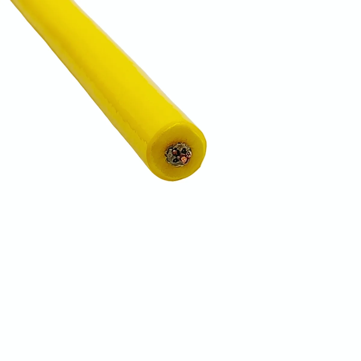
Double-sheath buoyant cable 2×0.5mm²+2×1SMF
Zero-buoyancy optoelectric cable with two 0.5mm² power cores and two single-mode fibres, LCP strength braid rated 100kg, foamed TPU sheath, 9mm OD.
Product overview
In underwater work, the weight of a cable is not a minor matter. A conventional cable keeps sinking once in the water, dragging along the bottom, trapping water and adding resistance, so the attitude of an underwater vehicle becomes hard to control and its working radius is limited by the catenary of the cable. A double-sheath buoyant cable introduces a foamed layer to bring the net weight of the cable in water close to zero, so that it hovers, rises and moves with the equipment instead of pulling it down.
A second benefit of this cable type is the division of duties inside the cable. Conducting, signalling, load bearing and buoyancy could all be pressed onto the same metal wire, but that forces the conductor to be enlarged, reduces flexibility and puts the signal on the same path as the current. This product separates the four duties: the copper conductor carries current only, the single-mode fibre carries signals only, high-strength fibre takes the tensile load and the foamed layer provides buoyancy. Each part works in its proper range, which makes the long-term reliability of small cross-section cores easier to guarantee.
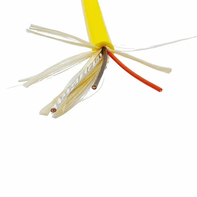
The product has a double-sheath construction: the yellow TPU outer sheath is easy to identify in water, and the foamed TPU inner sheath provides both buoyancy and cushioning. Two power cores and two single-mode fibres are laid in the same cable, which suits underwater equipment that needs power supply and data return at the same time.
Construction and materials
- Conductor: stranded bare copper, 0.5mm²
- Conductor diameter: 0.91mm
- Insulation: PE, 0.35mm thick, insulation diameter 1.6mm, red and black
- Fibre unit: 2 × 0.9mm transparent fibres, stranded in the same layer as the insulated cores
- Cabling: cabled diameter 3.2±0.2mm, with 6 × 3000D LCP fibres as fillers in the core
- Shield: aluminium foil wrap with a tinned copper drain wire brought out
- Strength braid: 1000D LCP fibre, 8+8 braid, 16 carriers, coverage approx. 50%
- Inner sheath: foamed TPU, 2.2mm thick
- Outer sheath: TPU, yellow, thin-wall extrusion
- Finished outer diameter: 9±0.5mm
Placing the fibres and the power cores in the same stranding layer is common practice for this kind of optoelectric cable. It gives a round cable and prevents the fibres from being squeezed to one side. The aluminium foil wrap with a tinned copper drain wire forms a continuous electrostatic shield that suppresses common-mode interference from subsea thrusters and variable-frequency drives; the outer LCP fibre braid both protects the foil from being rubbed through in the subsequent extrusion step and shares part of the tensile load in the longitudinal direction.
Layering a foamed inner sheath and a solid outer sheath is the core of the double-sheath design. The foamed layer is thick-walled and low in density and provides buoyancy and radial cushioning; the outer layer is thin, dense and responsible for abrasion resistance, hydrolysis resistance, scuff resistance and colour identification. Each layer does its own job, which avoids the dilemma of a single layer that is either too thick to float or too thin to wear well.
Key features
Buoyancy and weight balance. The foamed layer lowers the density of the cable body, so the cable is close to neutral in water and the equipment needs no extra ballast or floats to offset cable weight when hovering.
Combined optoelectric installation. Two power cores supply the equipment and two single-mode fibres carry control signals and video return; one cable handles both types of transmission, so handling gear, winches and bulkhead penetrations can be simplified.
Softness and bending. Conductors are stranded, the cabling layer uses a relatively loose lay and the fibres sit in the same layer as the cores, so the bending stiffness of the cable is kept low and it can pass over small sheaves and onto deployment drums.
Separated tension and conduction. Tensile load is taken by the LCP fibre fillers and braid, and the copper conductors take no load, so small cross-section cores are not drawn down or broken after repeated deployment.
Clearly divided sheath duties. The foamed inner layer provides buoyancy and cushioning while the solid TPU outer layer provides abrasion resistance and environmental isolation, so the construction stays intact after long-term immersion.
Electrical and mechanical performance
- Rated tensile strength: 100KG
- Rated voltage: as stated in the specification document confirmed by both parties
- Operating temperature: as stated in the specification document confirmed by both parties
- Minimum bending radius: as stated in the specification document confirmed by both parties
- Conductor DC resistance: as stated in the specification document confirmed by both parties
The tensile figure above is the load capacity of the cabled construction as a whole. Installation tension, dynamic shock and a safety factor should be taken into account in use, and the cable should not be run at full load permanently. Voltage class, temperature range and bending radius are confirmed by both parties in the specification document according to the actual working conditions, because different depths and deployment frequencies call for different sheath thicknesses and strength element configurations.
Typical applications
- Power and signal umbilicals for underwater vehicles (ROV/AUV), especially light equipment that has to hover and observe for long periods
- Composite cables for subsea cameras, lighting and pan-and-tilt systems, with power and video return on one cable
- Data and power channels for water quality monitoring buoys and subsea sensor arrays
- Sampling equipment, towed bodies and observation platforms in marine research
- Underwater inspection and survey equipment in reservoirs, lakes and aquaculture areas
- Inspection and cleaning tools for underwater structures such as gates, pipes and piles
Where the cable is deployed often and equipment attitude matters, neutral buoyancy gives the most direct benefit; for permanent fixed installations, hydrolysis resistance of the sheath and stability of the strength construction matter more.
Selection and customisation notes
1. Establish the required net weight in water first. Different depths and water temperatures correspond to different buoyancy requirements; if the equipment has limited reserve buoyancy, the foamed layer thickness can be adjusted further, subject to the specification document confirmed by both parties.
2. Confirm the fibre type and count. This construction is two single-mode fibres; multimode, a higher fibre count or additional copper signal pairs require the cabled diameter and buoyancy balance to be recalculated.
3. Confirm the load rating. The tensile figure should match the rated tension of the handling system; where necessary the number of fibre fillers or the braid coverage can be increased.
4. Confirm the termination method. Subsea connectors, vulcanised splices and breakout glands change the local outer diameter and weight distribution, and should be stated at the selection stage.
5. Confirm the operating environment. Long-term immersion, oil contamination, UV exposure and mechanical abrasion place different demands on the sheath material, and the outer compound and colour can be adjusted to the project conditions.
Delivery length, packaging, print legend and termination type can be agreed to project requirements. Before ordering, provide the installation route, deployment method and equipment power so that conductor cross-section, buoyancy configuration and connector type can be calculated together, avoiding a mismatch between cable weight and equipment reserve buoyancy on site.
Related in Zero-Buoyancy Cables
Engineering enquiry