PDK81301 2×0.75 mm² + 4×2×24AWG + 2×2×24AWG 50 kg Composite Power and Signal Umbilical Cable
Underwater Power Cables · Marine & Subsea
PDK81301
PDK81301 umbilical combining 2×0.75 mm² power cores with four and two signal pairs, each foil and braid shielded, TPU sheath, 500 N tensile strength.
Product overview
Waterproof cables are products designed for long-term immersion, frequent diving or high-humidity environments. The PAIDE Cable PDK81301 series composite power and signal umbilical combines low-voltage power circuits with multiple control and data signal circuits in a single cable body, so that underwater equipment can be supplied and can transmit signals over the same run. The series is specifically designed in four respects: conductor stranding, insulation tightness, shield coverage and outer sheath sealing. As a result the cable maintains stable electrical parameters and a long service life while withstanding external water pressure.
In principle, underwater and watertight cables share a common approach: encapsulation with potting compound, a PUR or TPU outer sheath, and water-blocking materials such as water-blocking yarn in the core. Depending on requirements, signal, power and fibre units can be combined in different configurations, and the applicable depth covers grades from ordinary shallow water to high-pressure deep water. The PDK81301 series follows this approach, combining power and signal units to meet composite transmission needs at the equipment end; where optical signals must also be transmitted, the series can be supplied in an optoelectric composite construction.
Construction and materials
The dimensions, materials and cross-sections of the models in this series are listed in this section; the following sections give qualitative descriptions only.
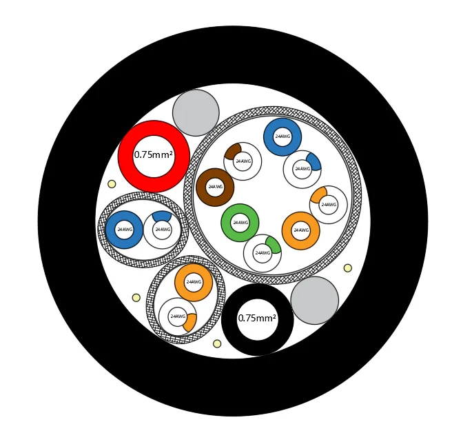
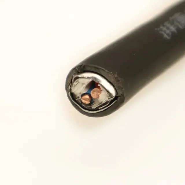
Taking PDK81301-2×0.75mm²+4×2×24AWG+2×2×24AWG as an example of the composite power and signal construction, the core is made up of three types of unit.
- Power unit: bare copper conductor, multi-strand stranded, stranded diameter 1.12±0.05 mm; PE insulation, average thickness 0.39±0.05 mm, minimum thickness 0.33 mm, insulation diameter 1.9±0.05 mm, identification colours black and red.
- Signal units: four signal pairs and two signal pairs, two types of paired unit; bare copper conductor, cross-section 0.22 mm², multi-strand stranded, stranded diameter 0.61±0.05 mm; PE insulation, average thickness 0.2±0.05 mm, minimum thickness 0.17 mm, insulation diameter 1.0±0.05 mm, standard identification colours.
- Shield: each signal group has a composite shield of aluminium foil plus tinned copper wire braid, combining high-frequency interference suppression with mechanical strength.
- Fillers: 4×1500D LCP fibre combined with PE rope fillers, used to keep the core circular and to improve longitudinal water-blocking.
- Outer sheath: TPU, black, average thickness 1.5 mm, minimum thickness 1.3 mm, finished outer diameter 10.3±0.3 mm.
The fibre composite model PDK81301-2×1.5mm²+2SMF-200KG is configured as follows: the power conductor is bare copper, multi-strand stranded, stranded diameter 1.59 mm; PE insulation, average thickness 0.50 mm, minimum thickness 0.43 mm, insulation diameter 2.6±0.1 mm, identification colours red and black; the fibre part is a two-core single-mode G657A2 unit with a helical armour protection layer, the fibre unit sheath is PVC with an outer diameter of 3.0 mm; the core is filled with cotton yarn and aramid fibre; the outer sheath is PUR, yellow, average thickness 1.2 mm, finished outer diameter 8.3±0.5 mm.
There is also the PDK81601 two-core fibre model, which uses single-mode armoured fibre. The fibre unit outer diameter is the same as that of the fibre composite model above, and both the inner and outer sheaths are LSZH, black. The average thickness of the inner sheath equals the minimum thickness of the PUR outer sheath of the model above, namely 1.0 mm; the inner sheath outer diameter is 5.0 mm, the outer sheath has an average thickness of 1.15 mm and a minimum thickness of 0.98 mm, and the finished outer diameter is 7.5±0.3 mm. The cable carries a steel wire braid layer.
TPU sheaths offer good abrasion, oil and hydrolysis resistance while retaining a degree of flexibility, which suits underwater work involving repeated deployment and continuous flexing; PUR and LSZH sheaths each place their emphasis on hydrolysis resistance and low-smoke zero-halogen performance and can be selected according to the operating environment.
Key characteristics
- Wide temperature range: covers use in cold-water regions and in equipment compartments where temperature rises occur.
- Good bending performance: the minimum bending radius is relatively small, which facilitates routing and coiling in confined spaces.
- Tensile capacity: meets the loads encountered in general lifting and deployment operations.
- Defined water pressure rating: the transverse underwater depth rating is determined by the construction and suits working environments with a certain water pressure.
- Water-blocking design: dense insulation, inter-group shielding and fibre fillers together reduce the possibility of water penetrating longitudinally along the core.
- Optional optoelectric composite: where optical signals must also be transmitted, a composite construction with an armoured fibre unit can be selected, so that power and communication are installed in one pass.
- Complete shielding: each signal unit has its own composite shield, backed by the overall outer sheath, combining interference immunity with sealing.
Electrical performance
This section lists the electrical and mechanical figures for each model.
The rated voltage of the power unit in the composite power and signal construction is 300/500 V; that of the fibre composite construction is 450/750 V. Maximum DC conductor resistance at 20 °C: 24.9 Ω/km for the power cores and 84 Ω/km for the signal cores in the composite power and signal construction; 13 Ω/km for the power cores in the fibre composite construction. Lower DC resistance reduces line drop over long supply distances and provides a stable reference potential for the signal circuits, so that power supply and data return can share one cable.
For fibre attenuation, the two fibre models share the same figures: no more than 0.5 dB/km at 1310 nm and no more than 0.3 dB/km at 1550 nm.
For mechanical and installation conditions, the minimum bending radius is 10D for the standard composite power and signal construction and for the PDK81601 fibre model, and 20D for the fibre composite model, where D is the cable outer diameter. On temperature, the composite power and signal construction is rated down to -40 °C and the fibre composite construction down to -30 °C, with +105 °C as the upper limit for both; the low-temperature flexibility limit of PDK81601 matches the composite power and signal construction, and its upper limit can be raised to +120 °C. In addition, the composite power and signal construction has a nominal tensile strength of 500 N and a transverse underwater depth rating of 5 MPa.
For composite cables, the shielding and spacing between power and signal units matter equally: the electromagnetic field produced by an energised power circuit will interfere with adjacent signal pairs if it is not handled properly, which is why each signal unit in this series has its own shield, backed by the overall outer sheath, to keep data return stable. Actual line drop and temperature rise must still be assessed together with installation length, ambient temperature and load current.
Fibre composite models
Where optical signals must be transmitted at the same time, the PDK81301 series can be supplied in an optoelectric composite construction; the 2SMF fibre composite model described above is one example: the fibre part uses a single-mode G657A2 unit with helical armour protection, the unit sheath is PVC, the core is filled with cotton yarn and aramid fibre, and the outer sheath is yellow PUR.
The series also includes the PDK81601 two-core fibre model, which uses single-mode armoured fibre, LSZH inner and outer sheaths and a steel wire braid layer that provides additional mechanical protection should the outer sheath be damaged.
The dimensions and performance figures of these two fibre composite constructions are listed together with those of the composite power and signal construction in the "Construction and materials" and "Electrical performance" sections and are not repeated item by item here. These constructions concentrate optical transmission and power supply in one cable body, reducing the number of separate fibre cables to be installed in an underwater system and simplifying deployment and subsequent maintenance.
Typical applications
Such cables are commonly used for the power supply lines of underwater cameras and lighting systems, the power and signal links of underwater manipulators and control units, data return from water quality monitoring and sensor devices, the combined power and communication channel of small underwater vehicles, and the power and data transmission of marine equipment and oceanographic instruments. In underwater systems that require long-distance, multi-circuit power and communication at the same time, an integrated power and signal construction reduces the number of joints and potential failure points that come with laying several separate cables, and simplifies deployment and maintenance.
Customisation and selection notes
When selecting, it is advisable to establish first the rated voltage, the number of cores and the cross-section, the number of signal circuits and shielding requirements, the required tensile strength, the pressure rating corresponding to the working depth, and the bending radius limits imposed by the installation method. For greater depths or more complex load cases, strength members and water-blocking measures can be added to the construction; where fibre and power run together, confirm that the armour type, outer diameter and attenuation figures of the fibre unit match the system requirements. If an existing model does not fully match the actual conditions, a custom requirement can be raised against a confirmed specification; PAIDE Cable will organise production and propose construction options based on the on-site installation conditions.
Related in Underwater Power Cables
 Custom
 Custom
 Custom
 Custom
Engineering enquiry