PDK81602-4×5mm²+2SMF-2T Zero-Buoyancy Electro-Optical Tether, 20000 N
Zero-Buoyancy Cables · Marine & Subsea
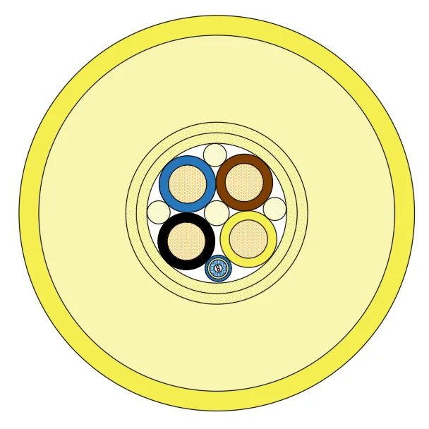
PDK81602
Zero-buoyancy electro-optical tether with four 5mm² power cores and two G657A2 fibres, 20000 N tensile strength and a dual TPU jacket.
Product overview
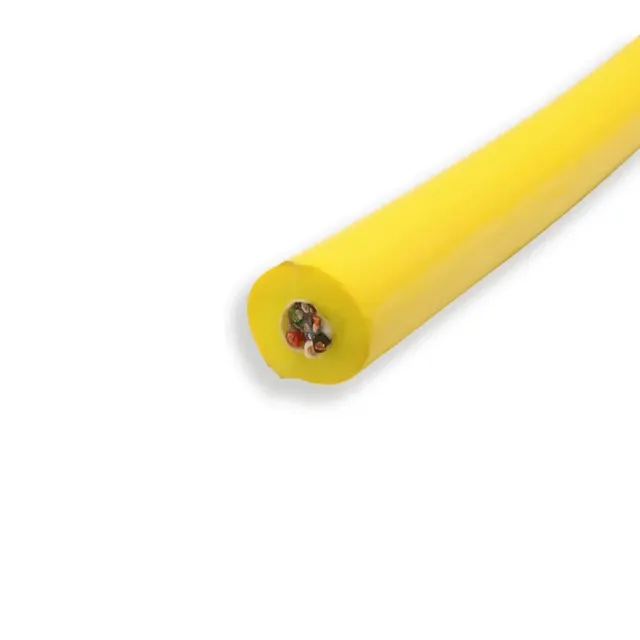
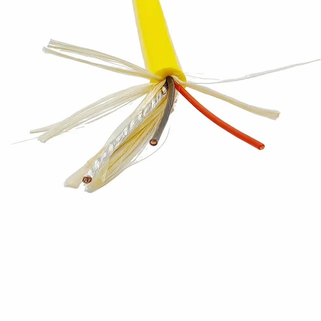
The PDK81602-4×5mm²+2SMF-2T is a zero-buoyancy cable in the electro-optical tether range: power cores and single-mode fibres share one cable body for underwater ROVs, underwater cameras and other subsea equipment, carrying power and transmitting signal and image at the same time. The cable is assembled from power conductors, a fibre unit, a tensile reinforcement layer and a dual-layer jacket to subsea service requirements; it carries mechanical pull and transmits electrical power and optical signals steadily, and is a typical underwater electro-optical towed tether.
Underwater equipment usually needs one tether that both supplies power and carries data. Video and high-speed data over metal cores alone are limited by transmission distance and external interference; adding fibre to the tether markedly improves the bandwidth and reach of the data channel, which makes real-time return of video and images feasible. Combining both in one cable also reduces the number of connectors on the equipment: only one cable has to be handled during launch and recovery, which lowers the risk of tangling and snagging.
Buoyancy and construction
Zero buoyancy is the defining feature of this product. The design uses a dual jacket: the inner jacket is foamed TPU, whose structure is filled with fine closed cells so that the average density of the cable in water approaches that of water and buoyancy is close to neutral; the outer jacket is solid TPU, which seals the foam layer from the surroundings, protects the core and provides an abrasion-resistant surface that resists sea water ageing. Working together, the two layers keep the cable from rising or sinking noticeably in water, reducing the extra pull and drag on the equipment during transit and deployment.
The cable is built up from the inside out as follows.
- Power conductors: four 5mm² bare copper conductors, stranded from fine wires, stranded diameter about 2.9 mm; flexible enough for cabling and bending.
- Insulation: PE, average thickness 0.7 mm, minimum point not less than 0.6 mm, insulated core diameter about 4.3 mm; the four cores are coloured brown, blue, black and yellow to identify phase and circuit on site.
- Fibre unit: two single-mode fibres, type G657A2, with armour protection, finished diameter about 2.0 mm, suited to long-distance optical transmission.
- Filler and reinforcement: Kevlar fills the gaps between cores to keep the core round. Tensile load is taken by two reinforcement layers, each wound from 19 groups of 3 × 3000D high-strength fibre, about 0.8 mm thick per layer; together they form a stable tensile skeleton, so the pull is carried mainly by the fibre and neither the fibre unit nor the power conductors are stretched during launch and recovery.
- Inner jacket: foamed TPU, average thickness 6.6 mm, minimum point not less than 5.6 mm, diameter after jacketing about 27 mm.
- Outer jacket: TPU, average thickness 1.5 mm, minimum point not less than 1.3 mm, finished diameter about 30 mm; jacket colour yellow for underwater visibility and surface inspection.
The mechanical and watertight ratings that correspond to this construction are: rated tensile strength 20000 N, sufficient for tethering medium-sized ROVs or heavier subsea equipment; minimum bending radius 15 times the finished diameter, which governs bending during launch, recovery and spooling and limits damage to the cable and the fibres inside; water depth rating 5 MPa, the pressure capability at the design depth. Confirm the actual working depth against the application and the engineering data.
Key features
- The comparatively high rated tensile strength meets the tethering needs of medium-sized ROVs or heavier subsea equipment; the pull is carried by the fibre reinforcement and neither the fibres nor the power cores are loaded directly.
- The rated temperature range covers both the low and the high end, so the cable adapts to a wide spread of ambient temperature and can be deployed in different seasons and waters.
- The minimum bending radius is set as a fixed multiple of the finished diameter; working to it during launch, recovery and spooling limits damage to the cable and the fibres inside.
- The water depth rating is the pressure capability at the design depth; confirm the actual working depth against the application and the engineering data.
- The TPU outer jacket offers good abrasion, oil, hydrolysis and UV resistance, suitable for long periods underwater or outdoors.
Electrical and optical performance
The power section is rated 0.6/1 kV, sufficient for medium-power subsea equipment. Maximum conductor DC resistance at 20 °C is about 3.7 Ω/km, so transmission loss is low and line drop over long supply distances is easier to control. The fibre section uses bend-insensitive single-mode fibre; together with the electro-optical conversion module on the equipment it provides bidirectional transmission of video and control signals, with bandwidth and reach clearly better than a metal conductor of the same size. The rated temperature range is -40 °C to +105 °C, so performance stays stable across waters and seasons with large temperature swings.
Because the electrical and optical paths are independent, they do not interfere with each other and can be maintained and tested separately; the insulation on the power side and the jacket on the fibre side each serve their own function, so a fault can be located per channel during servicing without replacing the whole cable.
Typical applications
Zero-buoyancy electro-optical tethers of this kind are commonly used with underwater ROVs, underwater cameras and other subsea equipment, and also suit ocean observation, lake and reservoir inspection, underwater structure inspection and aquaculture monitoring — anywhere power and live images are needed underwater. One end connects to the surface vessel or control platform and the other is deployed with the equipment; the cable follows the equipment in and out, and its neutral buoyancy keeps it spread out in the water so that it is less likely to foul thrusters or snag on obstacles.
In hovering, slow cruising or repeated launch and recovery, the in-water weight and flow drag of the cable directly affect vehicle attitude and power consumption; near-neutral buoyancy combined with flexible power conductors helps the vehicle stay stable and reduces the load on the thrusters. After use, coil the cable within its bending limits and check the outer jacket for cuts to extend service life.
Customisation and selection
Models in this series differ in core count, fibre count and tensile rating. Beyond the combination described here, smaller or larger power core sections, additional fibres or a different jacket colour can be selected. Cables can be built around the customer's working depth, equipment power, deployment method and handling gear; reference standards are applied as the customer requires, and standard print marking includes the company name, type and specification, date and metre marking for traceability.
Three points deserve checking at selection: whether the pressure and watertight requirements at the working depth are met; whether the tensile requirement derived from equipment weight and motion drag has enough margin; and whether the bending diameter of the handling gear meets the minimum bending radius. Where the duty involves frequent bending, towing or long static suspension, state the motion pattern and loads to the engineering team so that the reinforcement and jacket configuration can be assessed.
Related in Zero-Buoyancy Cables
Engineering enquiry